
Materials Performance Group
Research Publication |
|
PHYSICAL AND MECHANICAL PROPERTIES OF INTERMETALLIC COMPOUNDS COMMONLY FOUND IN SOLDER JOINTS R. J. Fields and S. R. Low III NIST, Metallurgy Division and G. K. Lucey, Jr. Harry Diamond Laboratories
Published in Metal Science of Joining, Proceedings of TMS Symposium, Cincinnati, Oct 20-24, 1991 Submission of the National Institute of Standards and Technology, not subject to copyright
ABSTRACT Three intermetallic compounds (Cu6Sn5, Cu3Sn, and Ni3Sn4) commonly found in solder joints have been prepared by gas atomization and then consolidated into bulk forms with microstructures similar to those observed in actual joints. Physical and mechanical properties relevant to the performance of joints have been measured for these materials. These data are evaluated in light of previously reported results, appropriate theories, and with regard to their applicability to actual layers in solder joints.
INTRODUCTION In every solder joint, between the solder and the substrate, a layer is present containing one or more intermetallic compounds [1,2,3]. This layer formed at the moment the joint was made, and was responsible for the resulting strong bond. It may also be responsible for problems in solderability [4,5] and may compromise the future reliability of the joint [1,2,6]. These layers are usually 1 to 5 micrometers thick and, depending upon conditions, may thicken with time [3]. As solder joints are made ever smaller, the intermetallic occupies an ever greater proportion of the whole joint. The day when the intermetallic layers represent 10-20% of the joint is fast approaching. What role do these layers play in the successful fabrication and reliability of joints? The answer to this question requires detailed analysis, modelling, and testing of simulated and actual joints. It is clear that certain physical and mechanical properties of the solder, intermetallic compounds, and substrate materials are needed for such an undertaking. Of these properties, those of the intermetallic compounds are the least well known. This paper describes materials properties determinations performed as part of a substantial program that has been underway for two years to prepare, purify, fabricate in bulk, and characterize those intermetallics that are most commonly found in solder joints. Care has been taken to produce the bulk material with grain sizes, chemistries, and crystal structures similar to those observed in actual joints. This bulk material has then been subjected to standard or otherwise well defined tests to measure the physical and mechanical properties thought to be most relevant to solder joints. We report here the elastic, plastic, and fracture behavior of Cu6Sn5, Cu3Sn, and Ni3Sn4. We also report the thermal expansion coefficients, thermal diffusivities, specific heats, thermal conductivities, electrical resistivities, and densities for some of these compounds. Comparisons with previously reported data are made and the applicability of the DuLong-Petit Law [7] and the Wiedemann-Franz Law [8] to these compounds is also examined.
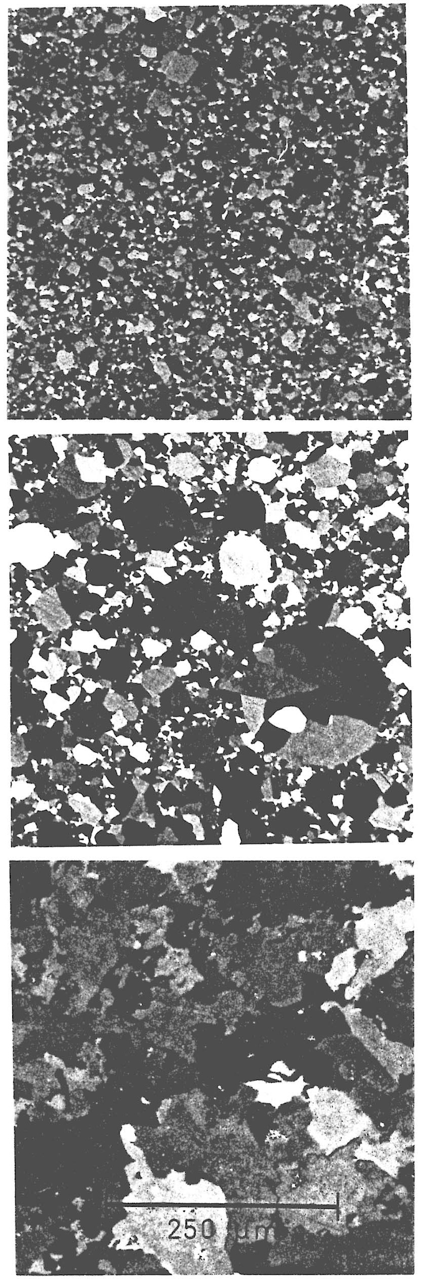
EXPERIMENTAL DETAILS Preparation of Bulk Material The presence of Cu6Sn5, Cu3Sn, and Ni3Sn4 at the interface between solder and copper or solder and nickel has long been known and often reported [1,2,3]. Despite this knowledge, few studies have been undertaken to measure important properties of these intermetallic compounds. The principal reason for this situation is that traditional preparation routes do not result in single phase material. Thus, solidification of a melt containing six parts copper and five parts tin will result in a solid body containing a mixture of Cu3Sn, Cu6Sn5, and Sn [9]. Attempts to homogenize this polyphase mixture by long term annealling results in extremely coarse microstructures which are completely unlike the fine grained materials observed in the interface layer. Every study of bulk intermetallics that we have evaluated to date suffers from a combination of the above difficulties (for example see references 10,11,12). A solution to the above problem, which was also the approach employed here, is rapid solidification by supersonic, inert gas, metal atomization. In this case, a melt of copper (or nickel) and tin in the correct proportions was forced through a small nozzle and blasted into micron-size droplets by a supersonic jet of argon as the stream of metal leaves the nozzle. These droplets cool extremely rapidly into a fine powder, often of the correct phase. If some phase separation does occur, it can only take place on the size scale of the powder particle which averages about 20 micrometers in diameter. Subsequent homogenization will not cause significant coarsening. To consolidate the resulting fine powder, it was encased in a thin-walled tube which was compressed under high pressure and at elevated temperatures until the material of interest was fully dense. The temperatures and times employed were neither high enough nor long enough to coarsen the material. A detailed account of this processing route to fine grained, single phase solder-based intermetallics is published elsewhere [13]. The microstructure of the resulting three intermetallics is shown in figure 1. The fine grain sizes are similar to those which have been observed in solder joints found on Standard Electronic Modules prepared under controlled conditions by the Solder Science Center at the Navy Weapons Support Center in Crane, Indiana. X-ray analyses confirmed that the materials prepared in bulk are single phase Cu6Sn5, Cu3Sn, and Ni3Sn4. Microscopy revealed the presence of some other phases, but these are present at concentrations very much less than 1% by volume. Low load (10 gram) microhardness tests were carried out on actual joint intermetallic layers and compared to the same type of microhardness tests on the bulk materials. The results were identical within one standard deviation of the measurements (which was about 5%). Therefore, the bulk materials prepared for the present studies were chemically, physically, and mechanically nearly identical to the intermetallics commonly found in solder joints. On this basis, the in-depth investigation reported here was pursued.
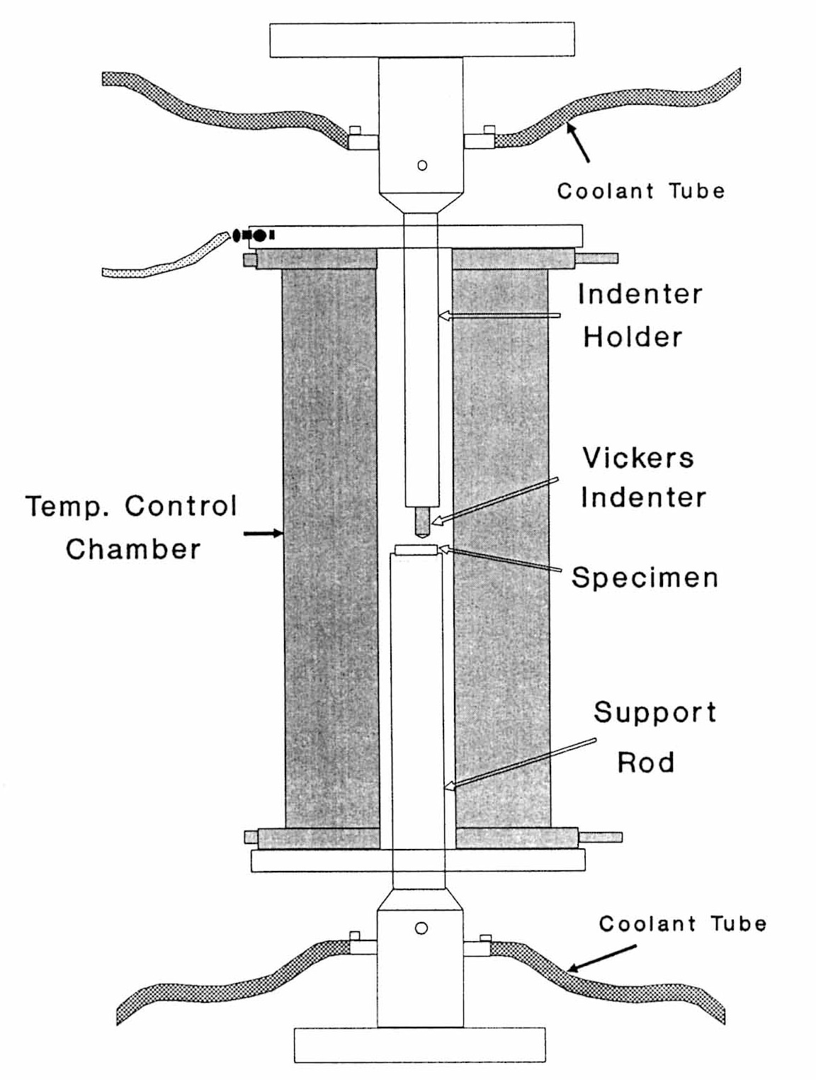
Mechanical Testing In surface mount technology, the solder is responsible for electrical continuity, heat conduction, and mechanical attachment. If it fails its mechanical attachment responsibility, the joint cannot be expected to perform its first two functions. Joint modelling efforts have been undertaken more and more in recent years as the growing importance of this mechanical aspect has been realized. However, these efforts have ignored the intermetallic layer which is known to be present and at which, or near which, failures are most often found [1,6]. Perhaps the simplest explanation for this apparent oversight is that, since there is practically no data on these layers, it is impossible to include them in a quantitative analysis. To perform even the most elementary analysis, one would need the elastic properties of the intermetallics. In the work presented here, not only are elastic properties reported, but also plastic properties (hardness) and the fracture toughness. This data set should allow interested investigators to generate considerably more realistic models of solder joints. The importance of intermetallic mechanical behavior may extend to the issue of solderability [4,5]. Pretinned leads are known to occasionally become unsolderable and exhibit dewetting during reflow. Of the many possible explanations for this, some involve the build up of stress or strain at the intermetallic layer. This results in decohesion at and oxidation of the interface, with a consequential loss in solderability. Other explanations include the possibility of cracking the intermetallic by thermal shock during reflow. To assess the likelihood that any of these phenomena actually impede solderability requires a knowledge of mechanical properties similar to that presented here. Intermetallics are often brittle and the ones studied here were no exception. For that reason, mechanical testing was carried out in compression and by indentation techniques. Compression tests were performed in accordance with ASTM E 9 (Test Method for Compression Testing of Metallic Materials at Room Temperature) [14] using cylinders having diameters of about 10 mm and lengths of about 40 mm. These cylinders were compressed axially at 20 micrometers/minute while their length and diameter were continuously monitored by gauges calibrated according to ASTM E 83 (Practice for Verification and Classification of Extensometers) [14]. These tests provided static or isothermal values of Young's modulus and Poisson's ratio at room temperature. Failure of the compression samples always occurred in the elastic portion of the stress-strain curve and so indentation tests were used to explore the plastic and fracture toughness behavior of these materials. Room temperature indentation tests were performed in accordance with ASTM E 92 (Test Method for Vickers Hardness of Metallic Materials) [14] using a commercial hardness tester. For tests above and below room temperature, a screw-driven tension/compression testing machine was fitted with a temperature controlled chamber and modified to perform Vickers hardness tests. This set-up is shown in figure 2. These tests were performed as closely as possible in accordance with ASTM E 92 [14]. The most significant variance in procedure was the time at peak load. In the present work, the peak load was held for 10-50 % of the recommended time. Nevertheless, the results obtained at room temperature on this modified machine agreed extremely well with those obtained on the standard hardness tester. The Vickers hardness is defined as the load on the indentor divided by the surface area of the resulting indentation. The results are traditionally reported in units of HV (Hardness Vickers) which are kg/mm2. It was also found that, at certain loads, the indentations exhibited cracking from their corners. This permitted a determination of fracture toughness. Anstis et al [15] have shown that the fracture toughness, KIc, is given by KIc = 0.016 (E/H)1/2(P/c3/2) where P is the load on the indentor, H is the hardness, E is Young's modulus, and c is the crack length measured from the crack tip to the center of the indentation. Note that this method is not an ASTM Standard Method and may therefore be considered only an estimate of KIc. Nevertheless, this method is used often used to measure the fracture toughness of brittle materials because of its simplicity.
Thermal Expansion Thermal expansion is one of the most important physical properties of these materials. Thermal expansion mismatches between adjacent layers are the primary source of stress or strain. Since a small change in temperature, dt, will cause a linearly related change in length, dl, the coefficient of linear thermal expansion, CTE, is defined as CTE = dl/(l0 dt) where l0 is the initial length of the object. The CTE may be a function of temperature, thus accounting for nonlinearities in the expansion behavior. Thermal expansion was measured dilatometrically between -50 and 200 C on bars of the intermetallic that were about 3 mm square and 50 mm long. The method used was ASTM E 228 (Test Method for Linear Thermal Expansion of Solid Materials with a Vitreous Silica Dilatometer) [14]. First, the room temperature length, l0, of a sample was measured with a micrometer. Then the sample was placed into a surrounding tube or holder with one end of the sample against the end of the tube and the other end of the sample against a spring loaded pushrod. The sample and tube slide into a cylindrical furnace. As the sample expands, the motion is transmitted out of the hot region to a room temperature region where it is detected by a distance transducer (linearly variable differential transformer or LVDT) mounted on the tube. Tube, sample, push rod, and transducer make up the expansion circuit; the transducer measures the amount that the sample and pushrod expand compared to the tube. The sample can be thought of as expanding in the gap of the circuit existing between the tube and the pushrod. Since the transducer measures the amount that the sample expands over and above that of the gap, it is necessary to determine the gap, or system, expansion. Calibration of the system expansion was performed by running the dilatometer over the same temperature range as the samples using Standard Reference Material 739 [16], a thermal expansion reference standard of vitreous silica certified by the National Institute of Standards and Technology (NIST).
Thermal Diffusivity Another property of interest is the thermal diffusivity. This property is useful in determining how fast the thermal loads are distributed and, thus, how uniform the thermal expansion will be as a function of time. Nonuniform thermal expansion will result in strains which, if constrained, may cause problems in a solder joint. The thermal wave method [17] was used to determine the thermal diffusivity of the three intermetallics. Because thermal wave propagation depends on the thermal diffusivity of the medium, this property can be derived from the spacial and temporal behavior of the wave. In the tests performed here, the thermal wave was produced by an argon laser beam aimed at the surface of a thin (100 to 200 micrometers) disk of intermetallic. Modulation of this beam by a mechanical chopper created a periodically varying temperature right at the surface. The thermal wave propagated through the intermetallic and was reflected at the back surface of the disk. The returning wave was sensed by a cooled InSb photovoltaic detector. The signal and phase of the detector signal were recorded by a lock-in amplifier, where the output of the laser beam modulator was used as the reference signal. The phase angle is related to the thermal diffusivity (a) by phase angle = tan-1{(2sin2x)/[exp(2x)-exp(-2x)]}+p0 where x = L(pi f/a) where L is the thickness of the disk, f is the modulation frequency, pi is 3.14..., and p0 is the phase offset. By carefully fitting the experimental data to these equations over a range of modulation frequencies, a value for the thermal diffusivity was be obtained. The thermal conductivity is the product of the thermal diffusivity, the density, and the heat capacity.
Heat Capacity The heat capacity was measured calorimetrically by means of a scanning differential calorimeter [18]. In this technique, the temperature of a reference pan and a pan containing the sample were raised at the same rate. Energy absorbed by the sample was compensated by adding an equivalent amount of electrical energy to a heater located in the sample pan. Platinum resistance heaters and thermometers were used in this calorimeter to accomplish the temperature and energy measurements in this method. The feedback loop that maintains the continuous and automatic adjustment of heater power necessary to keep the sample pan temperature identical to that of the reference pan also provided a varying electrical signal proportional to the varying thermal behavior of the sample. This electrical signal is a direct measurement of the energy absorbed by the sample as the temperature is raised. The slope of this energy versus temperature curve divided by the mass of the sample is the heat capacity at constant pressure, Cp.
Electrical Resistivity Since the primary function of solder joints is to provide electrical connection between the board and the component, the electrical resistance of the joint is important. Too high a resistance will result in signal attenuation. It will also cause ohmic heating that will add to the already high thermal loads of modern microelectronics. While solder is a relatively good electrical conductor, intermetallics have often been found to be poor in this regard. Two methods have been employed here to measure the resistivity of the intermetallics. All three intermetallics were studied by the van der Pauw method [19] and the Cu3Sn was also studied by an eddy current method [20]. The van der Pauw method measures the resistivity of flat samples of arbitrary shape and, so, was ideal for the intermetallics which were often difficult to form into long (300 mm) thin rods as required by ASTM B 193 (Standard Test Method for Resistivity of Electrical Conductor Materials) [14]. As in the van der Pauw method, contacts were made at four points on the periphery of a thin disk of arbitrary shape (approximately circular in the present case) of the material of interest. As required by this method, the disk did not have isolated holes. A current, A, of 4.5 amperes was passed through two of these contacts and the resulting potential drop (V1) across the other two contacts was measured. The current was then passed through a different combination of contacts and the voltage drop (V2) measured across the remaining two. The resistivity, r, is then given by r = (pi d/ln2) {(V1+V2)/2A} f(V1/V2) where d is the thickness of the disk, pi is 3.14..., and f(V1/V2)=1-.347{(V1-V2)/(V1+V2)}2-.092{(V1-V2)/(V1+V2)}4 In addition to the requirement that the disk be simply connected, i.e. it does not contain holes, the sample must be of uniform thickness, the contacts must be on the periphery, and the contacts must be small compared to the sample. These requirements were met. To provide some confidence in the above method, the resistivity of Cu3Sn was measured using a commercial eddy current conductivity meter. This method could not be used on the other intermetallics because their electrical conductivity was below the range of this meter. The eddy current method [20] measures the resistivity with a probe consisting of two coils. An alternating current in the primary coil induces an alternating field in the material of interest. This field induces a voltage in a pick-up coil. The voltage depends on the depth of penetration of the field into the material and the resistivity of the material. The frequency is adjusted to maintain a constant skin depth at all times regardless of material. Therefore, the frequency is directly proportional to the resistivity. This method requires calibration. By finding resistance standards very close to that of Cu3Sn, the resistivity of this material was determined with about 0 .5% accuracy and was found to be in excellent agreement with the value obtained by the van der Pauw method.
Density Density is a fundamental quantity which is used in many calculations such as converting thermal diffusivity to thermal conductivity, determining the loads induced by vibrations, deciding whether the intermetallic will sink or float in molten solder, etc. Furthermore, density must be consistent with the crystal structure or some discrepancy exists. The density was simply determined on precision ground cylinders of the intermetallic by measuring the dimensions and weighing the sample. In this case, cylinders about 10 mm in diameter and 30 mm long were used. Dimensional measurements were made to 0.01 mm. The samples were weighed on a balance capable of resolving 10 micrograms. The accuracy of this method was greater than the batch to batch variability in the materials. In general, the densities of several batches were determined and the average reported. The materials varied no more than 2% from batch to batch.
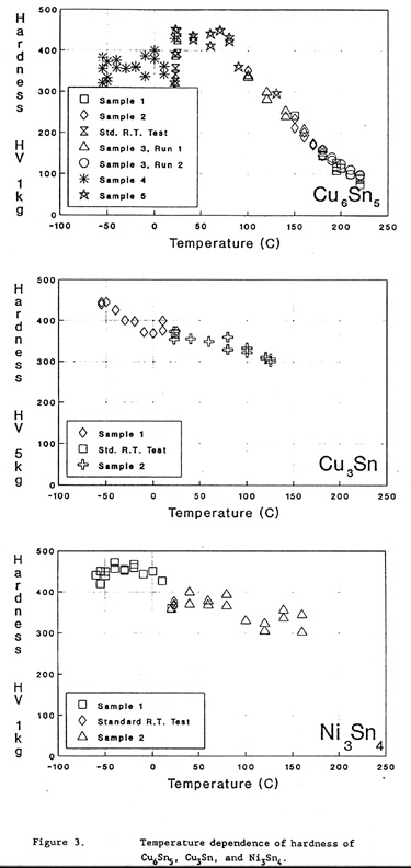
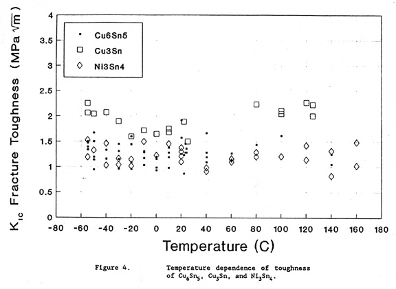
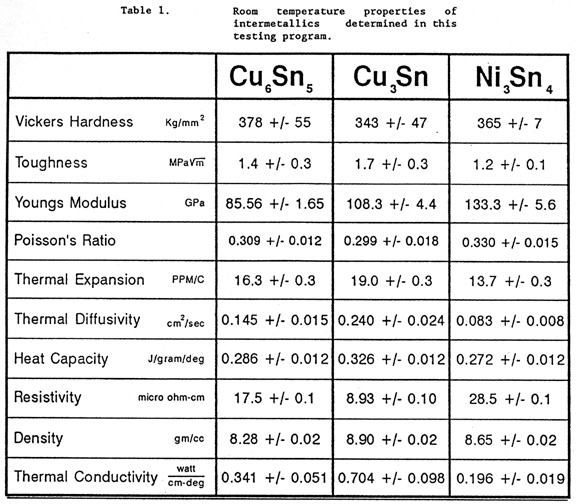
RESULTS The room temperature (20 C) results of all the studies performed are given in Table 1. All values are direct experimental quantities except for thermal conductivity which was calculated from the thermal diffusivity, the density, and the heat capacity. The temperature dependencies of the hardnesses of the three intermetallics are shown in figure 3a, b, and c. The variation in toughnesses of the intermetallics with temperature is shown in figure 4.
DISCUSSION The elastic moduli of these materials cannot in general be determined from those of the constituent elements. This is because the intermetallics are true compounds and not simply alloys of one metal with another. Young's moduli for Cu6Sn5 (85.56 GPa), for Cu3Sn (108.3 GPa), and for Ni3Sn4 (133.3 GPa), as reported here, may be compared with previously published values. Cabarat et al [10] used a resonant beam technique on bulk material to obtain Young's moduli of 102.38 GPa for Cu6Sn5 and 106.09 GPa for Cu3Sn. Subrahmanyam [11], using an ultrasonic resonant method, measured values of 85 and 80 GPa for Young's moduli of Cu6Sn5 and Cu3Sn, respectively. He also obtained shear moduli of 31 GPa for Cu6Sn5 and 27 GPa for Cu3Sn. Using our measured values of Poisson's ratio and Young's modulus, the shear moduli for these compounds may be calculated assuming that the samples are isotropic. On this basis, the shear modulus for Cu6Sn5 is 32.68 +/- 0.97 GPa, for Cu3Sn 41.69 +/- 2.27, and for Ni3Sn4 50.0 +/- 2.6 GPa. Agreement with the literature values of elastic properties seems good in some cases and not in others. Detailed reading of these two references, i.e.[10] and [11], revealed that the bulk samples were prepared by casting and annealing. Our experience with this processing route is that it produces coarse, multiphase material. The cited references did not investigate the actual condition of their samples. Ostrovskaya et al [21] vacuum deposited 20 to 60 micrometer thick layers of the intermetallic on a thin beam. The modulus of the intermetallic was determined from the change in resonant frequency of the beam due to the deposited layer. They found Young's moduli of 102 GPa for Cu6Sn5 and 153 GPa for Cu3Sn. They also reported that their samples contained a high density of defects. The values reported in the present research program are for single phase, fine grained material. The total error in determining these elastic data did not exceed a few percent. For comparison with typical substrates, the Young's and shear moduli reported here may be compared with 124 and 46.2 GPa, respectively for copper and 214 and 79.3, respectively for nickel [22]. The modest stiffness difference between the intermetallics and their associated substrates will induce some elastic inhomogeneity effect at the interface on loading. While the substrate/intermetallic elastic mismatch is relatively minor, the hardness difference is significant. All three intermetallics exhibit Vicker's hardnesses near 350 kg/mm2 (see Table I) which is similar to that for high strength steel and no plastic deformation is to be expected under the levels of stress that arise in solder joints. Copper, nickel, and solder are all much softer, having typical Vicker`s hardnesses of 30, 100, and 15 kg/mm2, respectively [23]. This plastic inhomogeneity will result in stress concentrations at or near the interface between solder and the intermetallic. This may be the reason that cracks usually run near the interface. For comparison to the data presented here, others [24-27] have measured the micro-hardnesses of thick layers of intermetallic grown between solid state diffusion couples of copper/tin or nickel/tin. In general, the agreement is excellent. The only real discrepancy is between one study's [24] hardness for Cu6Sn5 and our bulk value. As mentioned earlier, we also performed Knoop hardness tests on grown layers of the intermetallics following procedures similar to those used in [24]. In every case,the layer hardnesses agreed well with bulk hardnesses, i.e., we found no discrepancy for Cu6Sn5. Our 10 gm Knoop hardnesses were 555 +/- 35 for bulk Cu3Sn and 566 +/- 31 for the interface layer. Likewise, Cu6Sn5 exhibited a bulk hardness of 587 +/- 24 and the layer had a hardness of 567 +/- 32. The temperature dependencies of hardness as shown in Figures 3 a, b, and c indicate that hardness decreases rapidly with temperature in Cu6Sn5, but more slowly in Cu3Sn and Ni3Sn4. This behavior is probably due to the fact that Cu6Sn5 starts to melt at 415 C, where as Cu3Sn and Ni3Sn4 start to melt at 676 C and 796 C, respectively. The plateau or even slight decrease in hardness of Cu6Sn5 that is observed below room temperature cannot be explained at this time. Literature values for the toughnesses of the intermetallics are extremely scarce. Only one value for one intermetallic (Cu3Sn) was found [28]: 2.1 +/- 0.8 MPa m1/2. While this value is in agreement with the 1.7 +/- 0.3 presented here for Cu3Sn, the source for this datum gives no indication as to how the material was made, what its microstructure was, or how the measurements were carried out. In general, the toughnesses of these solder intermetallics are very low, being only two or three times that of glass. As seen in Figure 4, even increasing the temperature well above room temperature does nothing to mitigate the brittleness. The low toughness of the intermetallics combined with the tendency to concentrate stress at the interface layers must be viewed as undesirable. Some researchers have found that cracking either originates in the intermetallic layer or rapidly travels to it and then along it [1,6]. Perhaps the information reported here can be used in mechanical design of joints which minimize the stresses in the vicinity of the interface. Thermal expansion mismatch is often a source of stress in situations where the temperature changes. The values of thermal expansion coefficient (CTE) measured here do not indicate that mismatch is much of a problem. In comparison to 16.3 ppm/C for Cu6Sn5, 19.0 for Cu3Sn, and 13.7 for Ni3Sn4, the CTE for copper is 17.1 ppm/C while that for nickel is 12.9 ppm/C. On the other side of the interface from the substrate is solder. The CTE of solder depends on its composition, but ranges from 20 to 29 ppm/C. Based on this information, it would seem that the intermetallics expand very much like their associated substrate material, i.e. copper or nickel. Reichenecker [12] measured the CTEs for Cu6Sn5 and Cu3Sn to be 20.0 and 18.4 ppm/C, respectively. While the value for Cu3Sn is in good agreement with the present work, a significant discrepancy is noted in the case of Cu6Sn5. As reported in [12], tin peaks as well as Cu3Sn peaks were identified in x-ray analysis of the Cu6Sn5 produced in the earlier work, suggesting that the material was multiphase. Since tin has a relatively high CTE of 23, the presence of tin could account for the elevated value reported in [12] as compared to that found in the present work. Since these materials are metallic, the conduction of electricity is completely by electrons and the conduction of heat is predominantly by electrons. It is therefore expected that thermal conductivity and electrical resistivity are related by the Wiedemann-Franz law [8]. In Table 1, the thermal conductivity (which is the product of the measured thermal diffusivity, density, and heat capacity) is listed as 0.342 +/- 0.051 watt/cm/deg for Cu6Sn5, 0.698 +/- 0.098 for Cu3Sn, and 0.196 +/- 0.019 for Ni3Sn4. The thermal conductivities predicted from the resistivities using the above law are: 0.418 watt/cm/deg for Cu6Sn5, 0.820 for Cu3Sn, and 0.257 for Ni3Sn4. The agreement is well within the approximations in the law and suggests that the values of thermal diffusivity, heat capacity, density, and resistivity reported here are consistent for these compounds. These results give some support to the application of the Wiedemann-Franz law to other solder intermetallics if only the resistivity or the thermal diffusivity are known. A similar, fortunate situation exists for the case of the heat capacities. The law of Dulong and Petit [7] states that the heat capacity at constant volume (Cv) of solids is 1.51 J/gram-atom/degree C (6.3 calories/gram-atom/degree C. The statistical mechanics of harmonic oscillators [7] predicts that Cv of solids above their Debye temperatures should be 3 times the Universal Gas Constant, or about 1.41 J/gm-atom/deg. Using these predictions, the heat capacity for Cu6Sn5 should be between 0.0160 and 0.0170 J/gm/deg, for Cu3Sn between 0.0184 and 0.0194, and for Ni3Sn4 between 0.0153 and 0.0163. These values bracket the measured values of Cp (i.e., at constant pressure) listed in Table 1, thus providing support for the accuracy of the measured values. Note that Cv and Cp are usually within 5% of each other for solids [29]. It follows that the intermetallics studied here are above their Debye temperatures. Furthermore, it seems reasonable that this theoretical approach could be applied to other solder intermetallics that have not yet been studied or even produced in bulk form. The densities of the three intermetallics were calculated from a knowledge of their structures [30] to be 8.37 gm/cc for Cu6Sn5, 9.00 gm/cc for Cu3Sn, and 8.64 gm/cc for Ni3Sn4. These were straight-forward calculations for Cu3Sn and Ni3Sn4. In the case of Cu6Sn5, the stoichiometry differed from that for the prototypical NiAs structure. The above density was calculated by assuming that the naturally occurring vacant sites in the NiAs structure were occupied by Cu with a frequency necessary to obtain the correct stoichiometry. The measured densities agree well with the densities calculated from the crystal structures.
CONCLUSIONS Three intermetallics that commonly occur in solder joints have been isolated and produced in bulk forms. These bulk materials were shown to be chemically, physically, and mechanically similar to the actual intermetallic layers that form in solder joints. We report here the mechanical and physical measurements that were made on the bulk compounds. These materials were found to be extremely hard and brittle. Their elastic stiffnesses were similar to most substrate materials found in joints. Their heat capacities were well described by the Dulong and Petit Law and the Wiedemann-Frans Law accurately predicted the relation between the thermal diffusivity and electrical resistivity. The thermal expansion coefficients of these materials are between that of the substrate material and solder so that they behave more like a graded joint and little stress should develop due to thermal expansion mismatch.
ACKNOWLEDGEMENTS The authors would like to thank Dr. Hans Fredrikse for measuring thermal diffusivity, Dr. W. Boettinger for calculating the theoretical density of Cu6Sn5, Dr. G. Janowski for calculating the theoretical density of Cu3Sn and Ni3Sn4, Dr. K.L. Churney for determining the heat capacities, and Dr. M. Gvishi for measuring electrical resistivity by the van der Pauw method. The support of this work by the U.S. Army, Harry Diamond Laboratories is gratefully acknowledged.
REFERENCES [1] R. Chadwick, "The Influence of Surface Alloying on the Strength of Soft Soldered Joints," J. Inst. Metals 62 (1938) 277. [2] H. Swanger and A.R. Maupin, "Structural Changes in the Bonding Layer of Soft-Soldered Joints in Copper Pipe Line on Long-Continued Heating," Research Paper 1465, J.Res. National Bureau of Standards 28 (1942) 479. [3] Metals Handbook 9th Ed., Vol. 6: Welding, Brazing, and Soldering, publ. by Amer. Soc. for Metals, Metals Park, Ohio (1983). [4] P.E. Davis, M.E. Warwick, C. Chem, P.J. Kay, C. Eng, and S.J. Muckett, "Intermetallic Compound Growth and Solderability," Plating and Surface Finishing 70, (1983) 49. [5] M.E. Warwick and S.J. Muckett, "Observations on the Growth and Impact of Intermetallic Compounds on Tin-Coated Substrates," Circuit World 9 #4 (1983) 5. [6] J.O.G. Parent, D.D.L. Chung, and I.M. Bernstein, "Effects of Intermetallic Formation at the Interface Between Copper and Lead-Tin Solder," J. Mat. Sci 23 (1988) 2564. [7] F. Seitz, The Modern Theory of Solids, publ. by McGraw-Hill, New York, N.Y. (1949). [8] C. Kittel, Introduction to Solid State Physics, publ. by J.Wiley and Sons, New York, N.Y. (1968). [9] N. Saunders and A.P. Miodownik, "The Cu-Sn (Copper-Tin) System," Bulletin of Alloy Phase Diagrams 11 (1990) 278. [10] R. Cabarat, L. Guillet, and R. LeRoux, "The Elastic Properties of Metallic Alloys," J. Inst. Metals 75 (1949) 391. [11] B. Subrahmanyan,"Elastic Moduli of Some Complicated Binary Alloy Systems," Trans. Jap. Inst. Metals 130 (1972) 93. [12] W.J. Reichenecker, "Thermal Expansion of the Copper-Tin Intermetallic Compound Cu6Sn5 in the Temperature Range -180 to +200 C," Insulation/Circuits 27 #27 (1981) 104. [13] R.J. Schaefer, F.S. Biancaniello, and R.D. Jiggetts,"Intermetallic Compounds Formed in Solder Joints - Preparation of Single Phase Samples," Metal Science of Joining, Proceedings of TMS Symposium, Cincinnati, Oct 20-24, 1991. [14] 1991 Annual Book of ASTM Standards, publ. by American Society for Testing and Materials, Philadelphia, 1991. [15] G.R. Anstis, P. Chantikul, B.R. Lawn, and D.B. Marshall, "A Critical Evaluation of Indentation Techniques for Measuring Fracture Toughness: I, Direct Crack Measurements," J. Amer. Ceramic Soc. 64 (1981) 533. [16] NIST Sandard Reference Materials Catalogue, NIST Spec. Publ. 260, ed. by R.L. McKenzie, publ. by U.S. Gov't. Printing Office, Washington D.C., 1990. [17] H.R.R. Frederikse and X.T. Ying, "Heat Conductivity of Oxide Coatings by Photo/Thermal Radiometry between 273 and 1173 K," Appl. Optics 27 (1988) 4672. [18] M.J. O'Neill and A.P. Gray, "Design Considerations in Advanced Systems for Differential Scanning Calorimetry," in Thermal Analysis, Proc. of the Third ICTA, ed. by H.G. Wiedemann, publ. by Birkhaeuser Verlag, Basel, 1972. [19] L.J. van der Pauw, "A Method of Measuring Specific Resistivity and Hall Effect of Discs of Arbitrary Shape," Philips Res. Rpts. 13 (1958) 1. [20] Nondestructive Testing Handbook 2nd Ed, Vol. 4: Electromagnetic Testing, ed. by R.C. McMaster, P. McIntire, and M.L. Mester, publ. by Amer. Soc. for Nondestructive Testing (1986). [21] L.M. Ostrovskaya, V.N. Rodin, and A.I. Kuznetsov, "Elastic Properties of Intermetallic Compounds Produced by Vacuum Deposition," Soviet J. of Non-ferrous Metallurgy (TSVETNYE METALLY) 26 (1985) 90. [22] A.H. Cottrell, Mechanical Properties of Matter, publ. by John Wiley and Sons, New York (1964). [23] Metals Handbook 8th Ed., Vol. 1: Properties and Selection, publ. by Amer. Soc. for Metals, Metals Park, Ohio (1983). [24] D. Olsen, R. Wright, and H. Berg, "Effects of Intermetallics on the Reliability of Tin Coated Cu, Ag, and Ni Parts," Proc. 13th Annual Conf. on Reliability Physics, Las Vegas, pp 80-86 (1975). [25] R.J. Klein-Wassink, Soldering in Electronics, 2nd ed., publ. by Electrochemical Publications Limited, Ayr, Scotland (1989) 156. [26] L. Revay, "Interdiffusion and Formation of Intermetallic Compounds in Tin-Copper Alloy Surface Coatings," Surface Technology 5 (1977) 57. [27] B.D. Dunn, Metallurgical Assessment of Spacecraft Parts and Materials, publ. by Ellis Horwood Ltd., Chichester, England (1989) 287. [28] J. Hoyt, "Influence of Leg Shape and Solder Joint Metallurgy on Surface Mount Solder Joint Strength," Navy Weapons Center Technical Paper #6789 (1987) 409. [29] F. Reif, Fundamentals of Statistical and Thermal Physics, publ. by McGraw-Hill, New York (1965) [30] Metals Handbook 10th Ed., Vol. 8: Metallography, Structures, and Phase Diagrams, publ. by Amer. Soc. for Metals, Metals Park, Ohio (1973).
LIST OF FIGURES Figure 1. Microstructure of bulk, synthesized intermetallics: (a) Cu6Sn5, (b) Cu3Sn, and (c) Ni3Sn4. Grain contrast is due to the use of crossed polarizing filters. No etching is necessary as all three intermetallics are optically active. Figure 2. Modifications of screw-driven testing machine to perform high and low temperature hardness tests on the intermetallics. Figure 3. Temperature dependence of hardness of Cu6Sn5, Cu3Sn, and Ni3Sn4. Figure 4. Temperature dependence of toughness of Cu6Sn5, Cu3Sn, and Ni3Sn4.
LIST OF TABLES Table 1. Room temperature properties of intermetallics determined in this testing program. |
|
|
|
Materials Science and Engineering Division | [email protected] Home | Personnel | Research Opportunities The National Institute of Standards and Technology (NIST) is an agency of the U.S. Commerce Department. Privacy policy / security notice / accessibility statement / Disclaimer / Freedom of Information Act (FOIA) / No Fear Act Policy / ExpectMore.gov (performance of federal programs) / NIST Information Quality Standards |